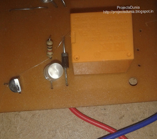
A Relay is an electromagnetically operated switch. Relays are used to control a circuit. Many relays consist a coil, a yoke, and an armature. When a current is passed through the coil, a magnetic field is induced in the coil which moves the armature and relay start its switching function. A normal relay has NO(normally open), NC(normally connected), COM and coil pin within it. A Simple one channel relay is shown in below image
 |
| Relay |
Required Components
For designing a relay driver circuit you will need following components
For designing a relay driver circuit you will need following components
- Relay
- 1N4007 Diode
- BC547 Silicon NPN transistor
- 10K Resistor
Circuit Diagram
A simple relay driver circuit is shown in below image. Here we use an NPN BC547 transistor to drive the relay.Base current ought to be a lot of enough to turn on a transistor. A diode 1N4007 use among the circuit to protect the transistor from damage due to back emf. When relay is in off state, COM pin of
 |
| Relay Driver Circuit |
a relay is connected to NC(normally connected) pin and when a small current start flows through relay coil then COM pin is connected to NO(normally open) pin.
NOTE: Change +5V to +12V in the circuit
NOTE: Change +5V to +12V in the circuit
Code for relay testing is same as for blink an LED so learn how to blink an LED and test your relay driver circuit. Now using relay make some more cool projects using arduino like control your AC home appliances, turn ON/OFF a bulb and many more.
Hope you like this article and give your valuable feedback by commenting below or if you have got any problem then also comment below.

SOmeone posted the illustration here: http://www.instructables.com/id/IR-Based-Home-Automation-Using-Arduino/
ReplyDeleteThanks for sharing...Relay Interface Card Suppliers in Chennai
ReplyDelete