Showing posts with label LDR. Show all posts

A Guide For Interfacing Analog Sensors With Arduino

By // 6 comments:
With Arduino, almost everything seems to be too friendly when it comes to interfacing various sensors, shields, add-ons or any other utility devices. Just because the Arduino coding environment is so user-friendly, anyone can do it. So in this post, I will just show you how to hook up your sensors to Arduino and get them running. Let's start with the very basics....

sensor interfacing with arduino
Sensors
What is Sensor
Sensors are those electronic components which convert physical data into electronic data. This data is in analog format and is fed to the microcontroller on the Arduino board. The microcontroller has inbuilt ADCs (Analog-2-Digital Converter) which processes this data and converts it into digital format.

And once you have received the (electronically converted) physical data, you can make your Arduino perform as you want.


On your Arduino board, there are analog pins named as A0, A1, A2, A3, A4, A5. The number of these pins may vary depending on your Arduino board. For UNO, there are only 6 analog pins while for MEGA there are 16. And remember this thing, any sensor (or other components) that gives analog data and you wish to process it, you'll have to connect it to your analog pins only. For now, I would say SENSORS would always be connected to analog pins.

Connection of Analog Sensor with Arduino
All sensors have their own method to connect with Arduino. Some of them need pull-up resistors, some need a certain power supply to use them.  But any sensor has generally 3 pins to connect to Arduino or other development board. These pins are. 
1. +Vcc
2. Signal
3. Gnd
Hook up the +Vcc to 5v (or 3.3v if sensor demands it) on your Arduino board.
Connect the Gnd pin to Ground pin on your Arduino.
Connect the Signal pin to any of your Arduino's analog pins. In our case, say A1.

Code for Interfacing Analog Sensor with Arduino
Below code is general code for interfacing analog sensors with Arduino. Write this code in your Arduino IDE to start playing with analog sensors.
void setup()
 {
  Serial.begin(9600);                            // initialize serial communication at 9600 bits per second:
  }

void loop() 
{
  int sensorValue = analogRead(A1);            // read the input on analog pin 1:
  Serial.println(sensorValue);                       // print out the value you read:
  delay(1);                                                      //this  delay in between reads for stability 
}

After burning this code to your Arduino, open the serial monitor and see the analog-2-digital converted data on your serial terminal. Basically, it is 10-bit data since the inbuilt ADC of your Arduino is a 10bit ADC.You will get the reading on your serial monitor.

That's all for now. Hope you got everything out of that blog.I'll try to bring something new next time. Till then........ keep learning and keep prototyping.

If You have got any problem or feedback then comment below. I will be right back to you soon.

Be sure to buy the stuff mentioned in this blog by clicking on the link below-

The vendor's offering interesting and working hardware at quite handy rates. Go give it a try! :)

Automatic Street Light Controller Circuit Using LDR And 555 Timer IC

By // 54 comments:
We are living in the world where everything goes to be automatic from your washing machine to your ceiling fan. Street lights are one of those examples of the automatic world. Automatic street light are those light which needs no manual operation to gets turn ON and turn OFF. Did you ever try to make such kind of street lights that gets turn ON and turns OFF automatically? In this article, we are going to make automatic street light using LDR and 555 timer IC.

List of Components  
  1. 555 Timer IC
  2. LDR
  3. LED
  4. Potentiometer
  5. Resistor 1* 1k ohm 
  6. Resistor 1* 220 ohm
  7. 9V Battery
  8. Printed Circuit Board(PCB) Or BreadBoard 
Circuit Diagram
A very simple circuit diagram of automatic street light is given below. 
automatic street light controller circuit using ldr
Automatic Street Light Controller Circuit

Principle and Working of Automatic Street Light Controller

555 Timer IC is the main part of the circuit that works as a comparator. All the working of this circuit depends on the working of the 555 timers Ic.To know more about 555 times IC read this article Working of 555 Timer IC. In this circuit pin, 3 produce output which has just two states high and low. Output goes to high when  trigger pin  is at a lower level than the 1/3rd level of the power supply voltage and output goes low when trigger pin 2 is at above then 1/3rd  of the power supply voltage. In this circuit pin, 4,6 and 8 are connected to the power supply. Here we use LDR to detect the presence of light which is formed a potential divider circuit with the help of 1k ohms resistor. LDR is a special type of resistor whose value depends on the light. Read this article to know How LDR Works. The output of this divider circuit is given to trigger pin of the 555 timer IC. 

In this circuit, we use a simple LED to know how the whole circuit works. You can also connect as much led as you want by using the transistor or you can connect a Relay to control high voltage electrical bulbs. 

You must use caution while connecting Relay to this circuit because its may be danger and as different bulb have different wattage.

Video Demonstration of Automatic Street Light Controller


How To Interface LDR With Arduino

By // No comments:
Hello, Friends hope all of you playing with your arduino and currently need to try to do another cool projects on arduino. Therefore, this tutorial is for you. During this tutorial, we interface LDR(Light dependent Resister) with the arduino board. It is very simple tutorials for arduino students, hobbyist, and beginners. Before going more we must find out how LDR is dependent on Light.

What is LDR 
interfacing ldr with arduino
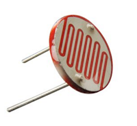
LDR(Light dependent Resister) or a photoresistor is a light dependent variable resistor that resistance decreases with the increase in the intensity of light. This gives an analog value so that it is connected to an analog pin of arduino board. A simple LDR is shown within the image and to buy an LDR click on the below image

Circuit Diagram
A simple circuit diagram is shown in the image. We won't use LDR directly within the circuit in order that a potential divider circuit is used with a 10K resistor. In this circuit one pin of LDR is connected to Analog pin A0 of arduino UNO and one pin is connected to ground(GND).

circuit diagram of LDR interfacing with arduino
LDR Circuit
Source code
Now connect your arduino board together with your PC and upload the given source code into the board. After uploading the code run your program and see the different value in your serial monitor.

LDR interfacing source code with arduino
LDR Code
Download:


Watch This Video: