Interfacing SPI TFT with Arduino.

By // 20 comments:
Hey fellas!
It's been long since our last blog...but worry not! Here I'm back again with something new to try this time around. This blog will let you know how to interface a 1.8 inches SPI TFT with arduino. The task may get a bit tricky if someone just starts without taking a few things in consideration. So here we go!


Now what's with this "SPI" term? Why not just a TFT?
Well, that's because like you all must have known, there are 2 modes of transferring data, SERIAL & PARALLEL. When there are separate multiple data buses for data transfer, that's a Parallel Data Bus TFT or more generally known as a normal TFT. These types of displays will have a comparatively large no. of pins to connect (quite obvious), as 8 or 16 pins are for data bus alone and then the other ones too.
They generally take up all the space on an UNO or even may require a shield as well.

When there is a single data bus to transfer all the data, all the data is streamlined in a series and then pushed towards the receiving end. This type of TFT is called an SPI TFT, where SPI stands for SERIAL PERIPHERAL INTERFACE. Now we know what that un-abbreviated form says!

Also remember that this 1.8 inches SPI TFT has different pin connections on an UNO (or similar) board and the MEGA board. On MEGA, the SPI pins lie at 50,51,52 and 53. 

First of all, list of required items is as follows:
* Arduino UNO (or similar) x 1
* 1k ohm resistances x 5
* One-2-One connectors x 8

The TFT library comes pre-installed in Arduino version 1.0.5 and later.

Make the connections as mentioned below-

Reset
8
Dc (A0)
9
Cs
10
SDA
11 (UNO) or 51 (MEGA)
SCL
13 (UNO) or 52 (MEGA)
BKL
3.3v
Vcc
5v
Gnd
Gnd


Now instead of making the first 5 connections directly to Arduino, put a resistor of 1k or similar value between the TFT pin and the Arduino pin. That’s because the IO ports are 3.3v tolerant while the Vcc required is 5v. It is quite possible because of it’s non-standard chinese manufacturing.

Now, open the IDE and run the any sketch except the “BitmapLogo”. This sketch uses the SD card function and requires you to hook up the TFT with an SD card as well, which is definitely not a part of this article.

I’m putting a demo sketch that I ran successfully-

#include <TFT.h>  // Arduino LCD library
#include <SPI.h>

// pin definition for the Uno
#define cs   10
#define dc   9
#define rst  8

// pin definition for the Leonardo
// #define cs   7
// #define dc   0
// #define rst  1

// create an instance of the library
TFT TFTscreen = TFT(cs, dc, rst);

// char array to print to the screen
char sensorPrintout[4];

void setup() {

  // Put this line at the beginning of every sketch that uses the GLCD:
  TFTscreen.begin();

  // clear the screen with a black background
  TFTscreen.background(0, 0, 0);

  // write the static text to the screen
  // set the font color to white
  TFTscreen.stroke(255, 255, 255);
  // set the font size
  TFTscreen.setTextSize(2);
  // write the text to the top left corner of the screen
  TFTscreen.stroke(255, 0, 0);
  TFTscreen.text("IoT Freaks!\n ", 20, 0);
  TFTscreen.stroke(0, 255, 255);
  TFTscreen.text("Sensor value\n ", 12, 25);
  // ste the font size very large for the loop
  
}

void loop() {

  // Read the value of the sensor on A0
  String sensorVal = String(analogRead(A0));

  // convert the reading to a char array
  sensorVal.toCharArray(sensorPrintout, 4);

  TFTscreen.stroke(255, 255, 0);
  TFTscreen.setTextSize(5);
  TFTscreen.text(sensorPrintout, 34, 50);
  delay(550);
  TFTscreen.stroke(0, 0, 0);
  TFTscreen.text(sensorPrintout, 34, 50);
}

This sketch requires a sensor at pin A0 to read it's value and then display it as text on  the TFT. So put any analog value sensor such as a potentiometer, an LDR, an IR pair or whatever you have.


Viola! I’m pretty much sure you’ll have it done then……

Be sure to buy the stuff mentioned in this blog by clicking on the link below-
http://www.ebay.in/usr/4d_innovations?_trksid=p2053788.m1543.l2754

The vendor's offering interesting and working hardware at quite handy rates. Go give it a try! :)

So until my next blog, this is it. As always, any problem you face and wish to discuss it, the comment boxes are always down there and you can reach me as well at iotfreaks@gmail.com

For more of these interesting stuff, like my page-
https://www.facebook.com/iotfreaks/

And our community,
https://www.facebook.com/projectsdunia/

How To Interface PIR Sensor With Arduino

By // 14 comments:
Hello Arduinians... Ever thought of detecting motion via your Arduino.... if yes, then this one's for you. In this tutorial, We're interfacing PIR sensor today with Arduino. Let's gets started!

Block Diagram
Working of PIR Motion Sensor
Block Diagram
Components Required For This Tutorials
  1. 1 * Arduino Board
  2. 1 * PIR Motion Sensor(you can buy from here)  
  3. Breadboard
  4. Jumper wires
  5. Battery

What is PIR motion sensor & how it works?

Basically, a PIR stands for "Passive Infrared Sensor". The sensor works on the principle of infrared waves' detection those are being emitted by human bodies. They are undetectable to us but can be discovered by the devices designed for such special purposes. I'm going to go just a little deep, enough to make you understand the internal operation.
When a body moves in front of a PIR sensor, the temperature of that place changes where the body has moved. If the body makes a further movement, the composition of infrared waves being received by the PIR from that region changes and since the reading is not the same as last reading, it generates a signal for the microcontroller and we work on it accordingly.


Circuit Diagram
We can easily interface PIR motion sensor with Arduino-like our other sensor. But it all depends on our logic of the code, how efficiently do we want to detect motion through it.
A PIR has 3 pins, just like any other sensor, Vcc, Signal & Ground pin. A very simple circuit of interfacing PIR motion sensor with Arduino is shown below
circuit diagram of PIR Motion Sensor
Circuit 
PIR Motion Sensor description
                                                                                          PIR Motion Sensor                                          
The 2 knobs are there too. One for adjusting sensitivity by increasing or decreasing the range of motion detection and another one for response delay. If you're using PIR in your home security, I strongly suggest you set the range at maximum (towards right). However, the detection range offered by a PIR sensor is good enough, like about 6 metres as I've tested it successfully.

Source Code
Here is a very simple code for this tutorial which only detects if there is ANY motion and triggers an LED for confirmation.Write below code into Arduino IDE and compile it.

int pirSensor=5;                                                     // connect sensor at pin 5
int led=13;                                                             // connect led at pin 13
void setup() 
{
   Serial.begin(9600);                                             // initialize serial
   pinMode(led, OUTPUT);                                  //  initialize led as output
   pinMode(pirSensor, INPUT);                            //  initialize sensor as input  
}

void loop() 
{
  int sensorValue = digitalRead(sensor);                // read sensor value
  Serial.println(sensorValue);                                 // print sensor value  
  delay(100);                                                          //  delay 100 miliseconds
  if(sensorValue > 600)
  { digitalWrite(led,HIGH); }
}

Now you can connect the signal pin to any analog pin also but for that, you'll have to check what values do you get on the serial monitor and which value do you wish to use as a threshold for triggering any LED, buzzer, etc.
Note that the sensor first takes some time for its calibration and after that it starts detecting motion. If any motion is detected, it triggers the LED on Arduino board and keeps searching for the motion for a certain amount of time. It only settles low if there is no further motion detected for that given search period (which can be changed in code). Giving a search window to your sensor, makes it's working more efficient and there are better chances for you to get non-erroneous functioning.
I too did both codes and both worked fine for me. Here's a snap!
PIR motion sensor circuit
Demo
So that's an end to our tutorial  for this time. Hope you enjoyed reading. If you liked this tutorial then don't forget it to share with your friends. I'll be back with more..... till then #happyDIYing

If you have any question or query or feedback regarding this tutorial then leave a comment below and we will solve those as soon as possible.

Be sure to buy the stuff mentioned in this blog by clicking on the link below-
http://www.ebay.in/usr/4d_innovations?_trksid=p2053788.m1543.l2754

The vendor's offering interesting and working hardware at quite handy rates. Go give it a try! :)

Learn How To Make A Digital Voltmeter Using Arduino

By // 12 comments:
Arduino is very popular and easy to use. With Arduino, we can do lot's of projects and experiment. So today we add one more projects in our Arduino project list. In this article, we are going to make a digital voltmeter.using an Arduino board. In this project, we measure the input voltage range between 0 to 50V by using the voltage divider. It is very simple to use Arduino as a voltmeter. Arduino UNO has  5 analog pin to read the input analog value. If we have an idea about reference voltage then we can easily measure the input voltage. Here we will use 5V as a reference voltage.
Block Diagram
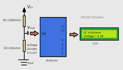
arduino based dc voltmeter circuit diagram
Block Diagram of DC Voltmeter
Component Required 
  1. 1 * Arduino Board(In this article we use Arduino UNO)
  2. 1 * LCD Module(Here we will use 16 * 2 LCD Module)
  3. 1 * 100K Resistor 
  4. 1* 10K Resistor
  5. 1 * 5K Potentiometer
  6. Some jumper wires
  7. Breadboard 
Circuit Diagram
Circuit diagram of this projects is very simple and easy to understand. Here we use a 16 * 2 LCD module to display the voltage. Read this article to learn How To Interface LCD With Arduino UNO.
arduino based DC Voltmeter circuit
Circuit Diagram
A voltage divider circuit is used here to divide the input voltage by the range  of Arduino board. As we all know that Arduino is compatible with till 5v only. Above this voltage, our Arduino may be damaged.
Analog input pin on the Arduino board measure the input voltage and convert it into digital format by using inbuilt ADC(analog to digital converter) that can be processed  by Arduino and then display it on LCD. In this project, we fed input voltage to analog pin A0 of Arduino by using the voltage divider circuit. A simple voltage divider circuit is made by using one 100kohm and one 10kohm resistor to make the 1:11 divider. Thus, by using this voltage divider circuit we can measure the voltage up to 55V.                      
         Voltage divider output  Vout  = Vin * ( R2/(R1+R2) )
It is good if you use this voltmeter project to measure the voltage within range 0v to 35v. Because large voltage may be damaged your Arduino board. 

Code 
In this project, we use inbuilt liquid crystal library for the display of voltage value and analogRead() function to read the input voltage at the analog pin A0. Here our reference voltage is 5V, hence we multiply read value with 5 and then divide it with 1024 to obtain the actual voltage. Then by using the voltage divider formula we can decrease this value within the range of Arduino board voltage.


Video Demonstration 

A Guide For Interfacing Analog Sensors With Arduino

By // 6 comments:
With Arduino, almost everything seems to be too friendly when it comes to interfacing various sensors, shields, add-ons or any other utility devices. Just because the Arduino coding environment is so user-friendly, anyone can do it. So in this post, I will just show you how to hook up your sensors to Arduino and get them running. Let's start with the very basics....

sensor interfacing with arduino
Sensors
What is Sensor
Sensors are those electronic components which convert physical data into electronic data. This data is in analog format and is fed to the microcontroller on the Arduino board. The microcontroller has inbuilt ADCs (Analog-2-Digital Converter) which processes this data and converts it into digital format.

And once you have received the (electronically converted) physical data, you can make your Arduino perform as you want.


On your Arduino board, there are analog pins named as A0, A1, A2, A3, A4, A5. The number of these pins may vary depending on your Arduino board. For UNO, there are only 6 analog pins while for MEGA there are 16. And remember this thing, any sensor (or other components) that gives analog data and you wish to process it, you'll have to connect it to your analog pins only. For now, I would say SENSORS would always be connected to analog pins.

Connection of Analog Sensor with Arduino
All sensors have their own method to connect with Arduino. Some of them need pull-up resistors, some need a certain power supply to use them.  But any sensor has generally 3 pins to connect to Arduino or other development board. These pins are. 
1. +Vcc
2. Signal
3. Gnd
Hook up the +Vcc to 5v (or 3.3v if sensor demands it) on your Arduino board.
Connect the Gnd pin to Ground pin on your Arduino.
Connect the Signal pin to any of your Arduino's analog pins. In our case, say A1.

Code for Interfacing Analog Sensor with Arduino
Below code is general code for interfacing analog sensors with Arduino. Write this code in your Arduino IDE to start playing with analog sensors.
void setup()
 {
  Serial.begin(9600);                            // initialize serial communication at 9600 bits per second:
  }

void loop() 
{
  int sensorValue = analogRead(A1);            // read the input on analog pin 1:
  Serial.println(sensorValue);                       // print out the value you read:
  delay(1);                                                      //this  delay in between reads for stability 
}

After burning this code to your Arduino, open the serial monitor and see the analog-2-digital converted data on your serial terminal. Basically, it is 10-bit data since the inbuilt ADC of your Arduino is a 10bit ADC.You will get the reading on your serial monitor.

That's all for now. Hope you got everything out of that blog.I'll try to bring something new next time. Till then........ keep learning and keep prototyping.

If You have got any problem or feedback then comment below. I will be right back to you soon.

Be sure to buy the stuff mentioned in this blog by clicking on the link below-

The vendor's offering interesting and working hardware at quite handy rates. Go give it a try! :)

Automatic Street Light Controller Circuit Using LDR And 555 Timer IC

By // 53 comments:
We are living in the world where everything goes to be automatic from your washing machine to your ceiling fan. Street lights are one of those examples of the automatic world. Automatic street light are those light which needs no manual operation to gets turn ON and turn OFF. Did you ever try to make such kind of street lights that gets turn ON and turns OFF automatically? In this article, we are going to make automatic street light using LDR and 555 timer IC.

List of Components  
  1. 555 Timer IC
  2. LDR
  3. LED
  4. Potentiometer
  5. Resistor 1* 1k ohm 
  6. Resistor 1* 220 ohm
  7. 9V Battery
  8. Printed Circuit Board(PCB) Or BreadBoard 
Circuit Diagram
A very simple circuit diagram of automatic street light is given below. 
automatic street light controller circuit using ldr
Automatic Street Light Controller Circuit

Principle and Working of Automatic Street Light Controller

555 Timer IC is the main part of the circuit that works as a comparator. All the working of this circuit depends on the working of the 555 timers Ic.To know more about 555 times IC read this article Working of 555 Timer IC. In this circuit pin, 3 produce output which has just two states high and low. Output goes to high when  trigger pin  is at a lower level than the 1/3rd level of the power supply voltage and output goes low when trigger pin 2 is at above then 1/3rd  of the power supply voltage. In this circuit pin, 4,6 and 8 are connected to the power supply. Here we use LDR to detect the presence of light which is formed a potential divider circuit with the help of 1k ohms resistor. LDR is a special type of resistor whose value depends on the light. Read this article to know How LDR Works. The output of this divider circuit is given to trigger pin of the 555 timer IC. 

In this circuit, we use a simple LED to know how the whole circuit works. You can also connect as much led as you want by using the transistor or you can connect a Relay to control high voltage electrical bulbs. 

You must use caution while connecting Relay to this circuit because its may be danger and as different bulb have different wattage.

Video Demonstration of Automatic Street Light Controller


Atmel AVR Studio - Download and Install

By // 2 comments:
In the previous article, we learn why AVR microcontrollers are so popular for designing embedded system projects. We have got the basic knowledge of ATmega16 Pin description and other required data through its datasheet. Now we can move forward to code our microcontroller. So In this article, we are going to install and setup the Atmel studio.
installing atmel studio
 Source: ATMEL

HOW TO INSTALL ATMEL STUDIO 


Those who have been using an earlier version of Atmel studio can realize that there are not so much difference between the new version of Atmel studio except the awesome UI. To download the atmel studio first you have to go to the atmel website or simply click here. There you may see two option for downloading atmel studio like this:
Software                   Description
    
     1                          Atmel studio (latest version name) eg. Atmel studio 7.0 (build 634) web installer                                   (recommended)
                                  2.38 MB, Required internet access during installation 

     2                          Atmel studio 7.0 (build 634) offline installer 
                                 734 MB, No internet access required during installation

Click any one option that you want to install and register your email id as a guest user or create an atmel account. Now go to your email account and click on the download link send by atmel.
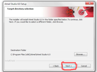
After downloading is completed then double-click on the installation file to install atmel studio. If you have got already installed Visual Studio then it will not install or if you do not have visual studio install on your desktop then first it install it.  Now you just click on next button till installation won't be finished.
When visual studio installation is completed then it installs atmel studio.Accept the terms of the license and click next.
installing atmet studio
Now click next once again as shown.
installing atmel studio
Now once again click on next button and installing will start as shown.
installing atmel studio 6
Now wait for a while and  click on finish button in next dialogue box. Now atmel studio installation is completed and atmel studio will be installed on your desktop. 
Now you have successfully completed installation of atmel studio and ready to code your AVR microcontroller. In the next article, we set up the atmel studio to write our first code for AVR  microcontroller. Hope you like this article and if you have got any problem then comment below.