How To Display Custom Characters On LCD Using Arduino

By // No comments:
We all are aware of custom characters used in the various display module.Heart, various style of smileys, arrow are the foremost usually used custom characters. Thus, during this tutorial, we are going to learn how to display custom characters in LCD using arduino UNO board. This project is done by using of arduino UNO board and 16*2 LCD module.

how to display custom character in lcd using arduino
Custom Character Display
It is assumed that reader knows how to interface LCD with arduino and how to install arduino software.We can generate a completely different style of the custom character using the below pixel array shown in the image. 
use of pixel array of lcd
Pixel array
the custom character shown below that is used in our program to generate the smile type character:
         {
                0b00000,
                0b00000,
                0b01010,
                0b00000,
                0b10001,
                0b01110,
                0b00000,
                0b00000
              };

Circuit diagram:
circuit diagram of display custom character in lcd
Circuit Diagram
Source Code:


Download:


Video:


Interfacing Push Button Switch to Arduino

By // No comments:
There are many electronic circuits can be used to interface with the device in the real world using switches as inputs. The simplest type of interfacing device is push button switches due to its low price and simple interfacing with any kind of electronic circuit. Push button switches are widely used in many electronic projects so knowledge of their interfacing is extremely essential in designing projects. So during this article, we learn how to interface push button switches with arduino. I hope you have knowledge about Arduino Board and led interfacing. Push button has four terminal and its allow current to pass through it when you press it down. 
push button interfacing
Push Button
Here we use PULL-UP or PULL DOWN resistor while using switches. PULL-UP register is a register connected between power supply and connector to give an electricity on certain condition.To understand the working of Pull-UP resistor look the image how its work.
working of pullup resistor
Pull-Up Resister
REED THIS ARTICLE  Interfacing LCD With Arduino UNO

Circuit Diagram
circuit of push button interfacing
Circuit Diagram
Source Code
code of push button interfacing
Source Code
Download

Download source code and circuit diagram file from here

Video


Arduino-based Automatic Temperature Fan Speed Controller

By // 37 comments:
In many small or large industry, you may have seen such a lot of fan that speed is control according to the temperature of the place. Thus, during this article, we have presented a demo of that application. It's assumed that you have an idea of how to read reading from the temperature sensor IC. In industry
temperature range will be more than 100 oC  but here we will work on the very low range.
Block diagram of Temperature control FAN

block diagram of temperature control fan using arduino board
Block Diagram
Required Components 
  1. Arduino UNO board (buy from here arduino )
  2. Temperature sensor IC LM35( buy from here LM35 sensor )
  3. DC Fan
  4. resistor 1* 1K
  5. 16*2 LCD Display
  6. Power supply  
  7. Diode(1N4007) 
Circuit Diagram 
In this application, we use an arduino board to control the speed of the fan and a 16*2 LCD display to display the status of the fan. Here we use a diode in parallel with FAN to prevent it from the damage and a 9V battery to provide power to the fan.

circuit diagram of arduino based temperature control fan
Circuit Diagram
Code
Again like our previous projects, code for this projects is also very simple. Here we use an analogRead() function to get the value of temperature sensor and store that value in the variable.When this value will exceed the min_temp value then the fan will start otherwise its always off. Download the file to get the source code of this projects along with its circuit diagram.
source code of arduino based temperature control fan
Source Code
Download
In the below link you will get all the file required for this projects.

Video Demonstration


How To Make a PC Control Robot

By // 9 comments:
Do you ever tried to control your robot using your PC or laptop? Controlling a robot using PC or laptop is often being a fun for the student or hobbyist. Thus during this article you will be tend to learn how to control your robot using your PC or laptop. Here it is assumed that you know How To Send Serial Data From Arduino To Laptop or PC and How To Receive and Send Serial Data Using Arduino Board. Thus lets begin to making this awesome DIY hack today with us.
controling a robot via PC using arduino board
Replica of robot

Component Required:

  1. Arduino UNO Board
  2. PC/Laptop
  3. L293D Motor Driver IC
  4. 2 Motor
  5. Serial Bluetooth Module
  6. 2 wheels
  7. Chassis
  8. Castor wheel
  9. Software (serial port software on your PC/laptop) 
Click here to see more projects on Arduino

Block Diagram:
Block diagram PC control robot using arduino
Block Diagram
Setup Connection For Robot:
circuit diagram of Pc control robot
Circuit Diagram
Here we use a L293D motor driver IC which is used for the controlling the rotation of the two motor connected to robot. Pin no 2,7,10,15 of L293D motor driver IC is connected to the pin no 9,8,7,6 of arduino board. Output pin 3,6,11,14  of the L293D motor driver IC is connected with the motor as shown within the Circuit Diagram Image.
L293D motor driver IC
L293D Motor Driver IC
For the connection of RX and TX read this article How To Receive and Send Serial Data Using Arduino Board 
NOTE:- Bluetooth Module should be removed while uploading the code from PC to Arduino board.

Code for PC Controlled Robot:

If you are beginner to arduino then download Arduino IDE from here How To Install Arduino Software On Windows. We use 9600 baud rate for the transmission of the data from PC/Laptop to Robot.Click here to Download the source code for PC controlled robot. 
code for the pc controlled robot
Arduino Code
We can control the robot using the following instruction 
'8' = Forward
'2' = Backward
'4' = Move Left
'6' = Move Right
'5' = Stop

Download:


Video:


If You have got any problem then be happy to comment in comment box or you can contact us at Facebook or Google+

Controlling LEDs With PC Using Arduino

By // 1 comment:
Wireless communication plays a very important role within the communication system. We may be able to send data from one point to another point simply through wireless communication. There is such a large option available for the wireless communication like Bluetooth, Wi-Fi etc. In this article, we concern only in Bluetooth. Bluetooth is a standard wireless technology which transfers the information over very short distances. It is assumed that you just ought to knowledge to How To Send Serial Data From Arduino To Laptop or PC and How To Receive and Send Serial Data Using Arduino Board

Controlling led via PC/Laptop

After Reading this article you will be able to control LED via your PC/Laptop. For controlling the led we use arduino board Introduction to Arduino Board

Circuit diagram:

Here we use three led blue, green and red that are connected to pin no. 10,9 and 8 of arduino board respectively. We also connect an LCD display module to arduino board. read this post for Interfacing LCD With Arduino UNO. All other connection for controlling led via PC is shown below image

circuit diagram for led control
Circuit Diagram
Program:

// ProjectsDunia
// http://projectsdunia.blogspot.in
// Our Facebook Page http://facebook.com/projectsdunia

//  control LED with your PC


#include <LiquidCrystal.h>

// initialize the library with the numbers of the interface pins
LiquidCrystal lcd(12, 11, 5, 4, 3, 2);
int blue_led=10;
int green_led=9;
int red_led=8;
int store=0;
void setup()
 {
    // set up the LCD's number of columns and rows: 
  lcd.begin(16, 2);
  // initialize the serial communications:
  Serial.begin(9600);
  pinMode(blue_led, OUTPUT);
  pinMode(green_led, OUTPUT);
  pinMode(red_led, OUTPUT);
  }
void loop()
{
  // when characters arrive over the serial port...
  if (Serial.available()) 
  {
    // save the data 
    store=Serial.read();
    switch(store)
    {
      case '1':
      lcd.clear();
      digitalWrite(blue_led,HIGH);
      lcd.write(" Blue_LED ON ");
      break;
      case '2':
      lcd.clear();
      digitalWrite(blue_led,LOW);
      lcd.write(" Blue_LED OFF ");
      break;
      case  '3':
      lcd.clear();
      digitalWrite(green_led,HIGH);
      lcd.write(" Green_LED ON ");
      break;
      case '4':
      lcd.clear();
      digitalWrite(green_led,LOW);
      lcd.write(" Green_LED OFF ");
      break;
      case '5':
      lcd.clear();
      digitalWrite(red_led,HIGH);
      lcd.write(" Red_LED ON ");
      break;
      case '6':
      lcd.clear();
      digitalWrite(red_led,LOW);
      lcd.write(" Red_LED OFF ");
      break;
      
    }
  }
}
  
Download:

LED control file

Video:


If you have any question, leave a comment below, Thanks for reading this article.If you like this article then support us by subscribing our youtube channel and like our facebook page.


How To Receive and Send Serial Data Using Arduino Board

By // No comments:
Serial communication is the easiest way to communicate with the peripheral device in embedded system. Thus, during this article, you may be able to learn the way to receive and send serial data from the arduino board. If you are beginner then first read this Introduction to Arduino Board and How To Send Serial Data From Arduino To Laptop or PC before moving on this article.
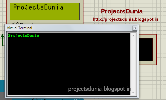
serial communication virtual terminal monitor
Arduino ide has such a big amount of inbuilt function for serial communication and detail of some function are here  How To Send Serial Data From Arduino To Laptop or PC. During this article, we tend to use some additional function that facilitates us to receive the serial data from the serial port. These functions are Serial.available(), Serial.read(), Serial.write whose explanation are given below:

1: Serial.available()

This function is always used before the Serial.read() function. This function returns always a positive value once reception is complete. This function is used for whether or not entire data is received.

2: Serial.read()

This function is used to read the received data from the serial port. We will save received data in any variable for any condition to ascertain.The variable could also be integer or character.

3: Serial.write()

This function is same as Serial.print() and Serial.println() explained in How To Send Serial Data From Arduino To Laptop or PC. This function returns the data to the serial port of the arduino.

Circuit diagram: 

circuit diagram for serial communication
Circuit Diagram
Code:
code for receiving serial data from laptop
Code
Download:


Video:


If you have got any question concerning this article then be happy to comment below or contact us via social network like facebook